In order to sustain stable power generation in a laser fusion reactor, it is necessary to repeatedly implode and ignite deuterium and tritium, which are the fuel of the reactor, with a laser. So, what kind of equipment is required to achieve this?
Currently, we are referring to a laser fusion reactor design based on a fast ignition method called LIFT (Figure 1). This design was proposed in 2017 by Professor Norimatsu’s team at the Institute of Laser Science, Osaka University
(original paper)。
First, a fuel target accelerated to a velocity of 100 m/s is injected toward the center of the reactor. As soon as the target reaches to the center, lasers irradiate the target from all directions to implode the fuel target, and another laser is irradiated to the fuel to induce a fusion reaction. The neutron energy produced by the fusion reaction is absorbed by a device called a “blanket” surrounding the center of the reactor. Then, the energy is converted to electrical energy by heating water in a heat exchanger to turn a turbine. When the cycle from target injection to fuel ignition can be stably repeated at a frequency of 10 times per second, it is believed that the system can be operated as a power plant.
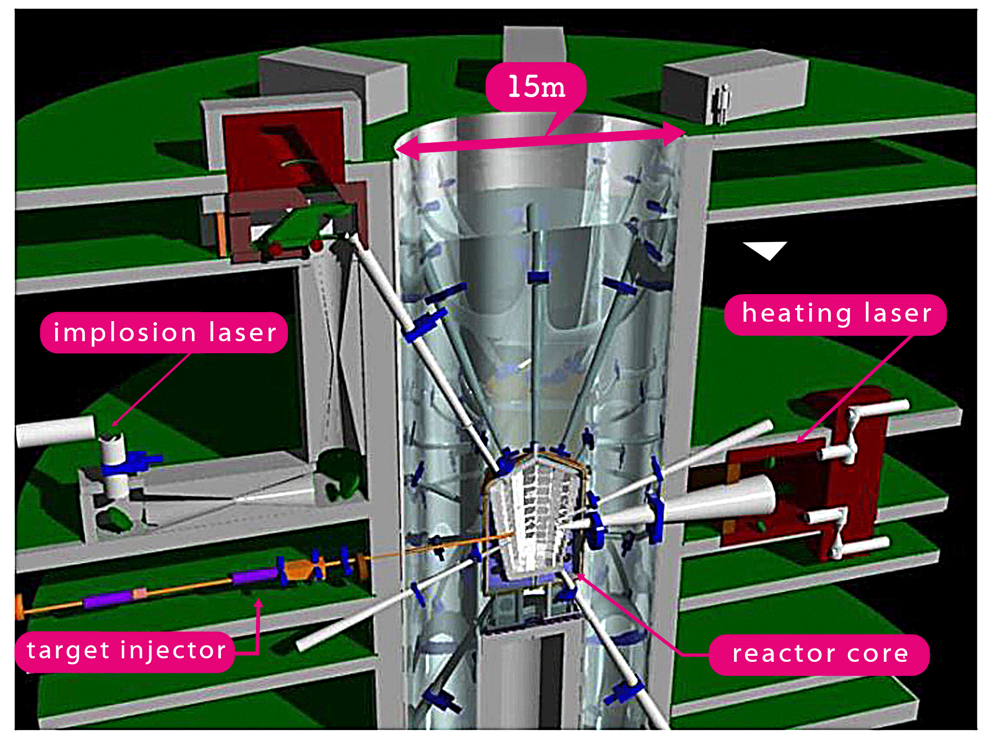
figure1. Conceptual Design of Laser Inertial Fusion Test Reactor (LIFT)
To achieve this, we need a system with following functionalities
- repeatedly fuel target injection at a fixed cycle
- calculation of the trajectory and tracking of moving targets with a laser.
In collaboration with the Graduate School for the Creation of New Photonics Industries, we have developed a system that repeatedly drops a dummy target (1 mm diameter stainless steel ball) at a frequency of 10 times per second. The trajectory of the target is calculated with optical sensors and a dedicated circuit, and irradiates a laser to the predicted position and timing.

figure2. Proof-of-Concept system for target
injection and laser tracking
Several hundred of dummy targets (② in Figure 2) are placed in the target feeder (① in Figure 2) and dropped one by one at a frequency of 10 times per second. Figure 2 shows how the falling dummy targets are detected by the sensors and irradiated with a laser. When the falling target passes the tracking sensor (③ in Figure 2), the output signal from the sensor is sent to the laser tracking device (④ in Figure 2). The device measures the time difference between the signals from the tracking sensors and calculates the time it takes to reach the position where the laser is irradiated from this time difference. This allows the laser to be irradiated in accordance with the timing of the arrival of the target at the laser irradiation position. However, the position of the target at the laser irradiation position has a fluctuatation of a few millimeters caused by a small error in the manufacturing process of the target delivery device and changes in the friction between the sphere and the device. Also, similar fluctuation are likely to occur in the LIFT system as well. Therefore, the laser tracking device is important. The tracking sensor measures not only the passing time of the target, but also its passing location. From the measured passing position, the laser tracking device calculates the positional deviation. The laser path has multiple reflecting mirrors, and the angle of a mirror can be remotely controlled by a motor (⑤ in Figure 2). Based on the calculated deviation of the position, the angle of the reflecting mirror can be controlled to irradiate the laser at the center of the falling target. Both a shadow of the target and the laser were captured by a camera (⑥ in Fig. 2), and the center of the shadow and the center position of the laser were determined by image analysis. They coincided with a high degree of accuracy. Since this is still a proof-of-principle experiment, the dummy target irradiated by the laser is not eliminated and captured by the target recovery device (⑦ in Fig. 2), and is sent back to the target supply device. So far, this system has been operated stably for at least 2 hours.
In the future, we will develop the following functionalities
- Inject the targets at higher speeds.
- Use a large mirror to track the target so that experiments can be conducted with high-power lasers.
- Increase the number of lasers
- Operate the system stably for a longer period of time
———-
LIFT figure(1) source
T. Norimatsu et al 2017 Nucl. Fusion 57 116040
https://iopscience.iop.org/article/10.1088/1741-4326/aa7f07
Y. Mori et al., Fusion Sci. & Technol. vol. 75, 36 (2019).
https://doi.org/10.1080/15361055.2018.1499393
Y. Mori et al., Nucl. Fusion vol. 62, 036028 (2022).
https://doi.org/10.1088/1741-4326/ac3d69